


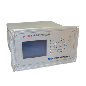
PRODUCT SHOW
SAI-228D capacitors protection and monitoring device
1 . Function Deployment
Protection
Function Model SAI-228DC SAI-228DD
Three- phase overcurrent definite time √ √
Inverse phase overcurrent ( in general, very, extremely ) √ √
Overvoltage protection √ √ alarm or trip
Low-voltage protection √ √
Unbalanced voltage alarm or trip protection √
Unbalance current alarm or trip protection √
Non-power protection √ √
2 . Description
2.1 Three- white overcurrent
The three sections of white over-current protection device is provided , Ⅰ, Ⅱ, Ⅲ fixed time limit, and white can also inverse time overcurrent protection . Either definite time or inverse time , each segment cast back control value (I1nf, I2nf, I3nf) can be controlled independently of each segment usage. Cast back control setpoint value means:
0 : Exit 1 : Inputs
Overcurrent protection features soft white plate , only the soft plate and cast back into the control values are given , the corresponding stages before investment.
2.1.1 Inverse time characteristics
White overcurrent protection characteristics selection setting Ifsx be selected for definite time or inverse time protection:
0 : Exit , 1,2,3 : Inverse time ( corresponding to the following ( 1 ) , ( 2 ) and ( 3) ) .
Choose to use one of the following three criteria inverse time characteristics . Inverse time characteristics for the current reference value IP and white inverse time protection current reference value Ii, tP inverse characteristic time constant for the white anti-time protection time constant tIi.
Normal inverse characteristics :
Very inverse characteristics :
Extremely inverse characteristics :
2.2 Overvoltage Protection
To prevent the system steady overvoltage damage caused by capacitors , the device has over-voltage protection, voltage taken from the capacitor bus PT voltage over-voltage protection features cast back control value UHnf, values have the following meanings :
0 : Exit 1 : Alarm , 2: tripping.
When max (UAB, UBC, UCA) is greater than the setting value , the overvoltage protection by setting delay action .
Over-voltage protection features soft plate trip , only soft plate and cast back into the control values are given , the corresponding trip protection was put in ; over-voltage alarm input control word can only generate an alarm event .
2.3 Low Voltage Protection
To prevent system failures caused by disconnecting the line after losing power capacitor bank , and bus lines overlap and so charged , the capacitor Photos
Closing low voltage withstand damage , low- voltage protection device is provided .
Low-voltage protection features cast back control value ULnf, values have the following meanings :
0 : Exit 1 : loss of pressure + low-voltage protection , 2 : After the current low-voltage lockout , 3: pure low-voltage
Loss of pressure + low voltage protection conditions are:
1: The circuit breaker together bits
2: The three -phase voltage is less than the low-voltage protection setting
3: When U1 <0.15Un, Imax <0.02In or when U1> 0.15Un, U2 <8V.
Low-voltage lockout protection by current conditions are:
1: The circuit breaker together bits
2: The three -phase voltage is less than the low-voltage protection setting
3: The three current value is less than the current value of closed lock
Pure low- voltage protection conditions are:
1: The circuit breaker together bits
2: The three -phase voltage is less than the low-voltage protection value and greater than 0.15Un
2.4 unbalanced voltage protection
Capacitor banks in order to prevent the breakdown of internal capacitor , the device is provided with unbalanced voltage protection. Unbalanced voltage protection features cast back control value UHnf, values have the following meanings :
0 : Exit 1 to 2: inputs - 1: Alarm , 2: tripping.
Unbalanced voltage is greater than a given value, the unbalanced voltage protection by setting delay action .
Unbalanced voltage protection features soft plate, only the soft plate and cast back into the control values are given , the corresponding trip protection only cast
Income ; unbalanced voltage alarm input control word can only generate an alarm event .
2.5 unbalance current protection
Capacitor banks in order to prevent the breakdown of internal capacitor , the device is provided with a current imbalance protection. Unbalanced current protection has cast back control value IHnf, values have the following meanings :
0 : Exit 1 to 2: inputs - 1: Alarm , 2: tripping.
Current imbalance is greater than a given value, the unbalanced current protection by setting delay action .
Unbalanced current protection features soft plate, only the soft plate and cast back into the control values are given , the corresponding trip protection only cast
Income ; unbalance current alarm input control word can only generate an alarm event .
2.6 Non- electrical protection
A non-electric device access , non-power 2 Action contacts , set an alarm or trip control value FDL1nf, FDL2nf, and action delay tFDL1, tFDL2.
If the alarm or trip control setting value is 0, no letter is not tripped.
After the non-electricity a contact closure , after tFDL1 delay, if FDL1nf = 1, then a trip command, and letters ; If FDL1nf = 2, then an alarm signal.
After the non-power 2 contact closure , after tFDL2 delay, if FDL2nf = 1, then a trip command, and letters ; If FDL2nf = 2, then an alarm signal.
Non-power protection plate with a soft , flexible plate only when the corresponding control inputs and set the correct word , the corresponding protection was put into .
2.7 System abnormal condition alarm and lockout
2.7.1 bus PT break alarm
Meet any of the following one , issued by the delay device bus PT break alarm signal.
⑴ positive sequence voltage U1 < when 0.15Un, any phase current > 0.04In
⑵ negative sequence voltage U2> 8V.
2.7.2 Control loop break alarm
TWJ and HWJ same time is 1 or 0 , after the alarm delay .
3 . Device tuning
Including soft plate tuning device , the device settings and device parameters in three areas , see 3.1, 3.2 and 3.3 .
Tuning should follow the relevant regulations , the device has special requirements in the relevant notes. Device parameters without special needs , it is desirable default values listed in the table . No protection, it should control the value to 0 - exit.
3.1 Soft- plate tuning device
Model SAI-228DC SAI-228DD
Three sections of white over-current protection √ √
Overvoltage protection √ √
Low-voltage protection √ √
Capacitor voltage unbalance protection √
Capacitor unbalance current protection √
Non-power protection √ √
Note : Soft plate only two values: inputs, quit. When the device is shipped , soft plate are tuning to quit.
3.2 Device setting value
No. Name Symbol tuning range Remarks
A phase
Between
Live
Flow
Insurance
Care segment segment Ⅰ Ⅰ phase overcurrent protection cast back control I1nf
2 white overcurrent stage Ⅰ current value I1 0.5 ~ 100A
3 Section Ⅰ phase overcurrent delay setting tI1 0.01 ~ 9.99S
4 Ⅱ Ⅱ segment segment phase overcurrent protection cast back control I2nf
5 phase overcurrent Ⅱ segment current value I2 0.5 ~ 100A
Ⅱ paragraph 6 white overcurrent delay setting Ti2 0.1 ~ 9.99S
Section 7 Ⅲ Ⅲ phase overcurrent protection section cast back control I3nf
8 white overcurrent stage Ⅲ current value I3 0.5 ~ 100A
9 segment Ⅲ phase overcurrent delay setting Ti3 0.1 ~ 60S
10 Inverse Inverse time protection features alternate control word Ifsx 0 ~ 3 Note 1
11 white inverse time protection current reference value Ii 0.5 ~ 100A
12 white inverse time protection time constant tIi 0.1 ~ 99.99S
13 Public
PT value break detection cast back control PTDXbs
14 low-pressure phase overcurrent closed lock invalid value ULbs 2 ~ 120V
15 over-voltage protection over-voltage protection alarm or tripping cast back control UHnf 0 ~ 2 Note 2
16 Over-voltage line voltage setpoint VUH 20 ~ 150V
17 Overvoltage Delay setting tUH 0.1 ~ 99.99S
18 Low Voltage Protection Low Voltage Protection cast back control ULnf 0 ~ 3 Note 3
19 low- voltage line voltage setpoint VUL 10 ~ 100V
20 Low-voltage protection delay setting tUL 0.1 ~ 99.99S
21 low-voltage current closed lock value Ilbs 0 ~ 10A
22 unbalance protection unbalance protection alarm or tripping cast back control Ubphnf 0 ~ 2 Note 2
23 unbalanced voltage setpoint Ubph 2 ~ 160V
24 unbalance protection time delay setting tUbph 0.01 ~ 9.99S
25 non-power
Protection of non- power cast back a trip or alarm control FDL1nf 0 ~ 2 Note 4
26 non-power a delay value tFDL1 0.1 ~ 99.99S
27 non-power trip or alarm 2 cast back control FDL2nf 0 ~ 2 Note 4
28 non-power two delay setting tFDL2 0.1 ~ 99.99S
Note :. 1 Ifsx values have the following meanings :
0 : Exit 1 to 3 : Inverse - 1: General , 2 : very , 3: Extreme
. 2 Ubphnf, Ibphnf, and UHnf values have the following meanings :
0 : Exit 1 to 2: inputs - 1: Alarm 2 : Trip
. 3 VUL values have the following meanings :
0 : Exit 1 to 2: inputs - 1: The loss of pressure + low -voltage protection , two by current blocking low-voltage, low-voltage 3 pure
. 4 FDL1nf and FDL2nf values have the following meanings :
0 : Exit 1 to 2: inputs - 1: Trip 2 : Alarm
3.3 device parameter tuning
No. Name Symbol Range step
A device -level management device mailing address ADDR 1 ~ 110 1
2 operation of the device password is PASSWORD 0 ~ 99 1
3 baud baud rate setting BTL 0 ~ 9 1
4 AC rated CT primary current rating of the amount Sec.IN 0 ~ 65535A 1A
5 PT primary current rating Sec.UN 0 ~ 999.9KV 1 KV
4 . Protection Principle wiring diagram
