


PRODUCT SHOW
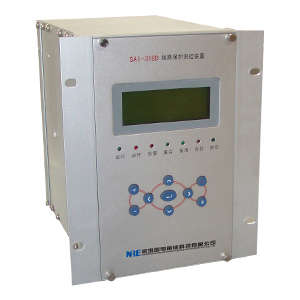
SAI-318D digital line protection and control devices
An Overview
SAI-318D digital line protection and control devices based on current, voltage protection and three-phase reclosing of circuit protection device sets the basic configuration. Applicable to 66kV and below voltage direct grounding system or non-resistance grounding system in the direction of the line protection and monitoring, can be installed in the switch cabinet in place, but also set the screen installed in the control room.
Protection configuration
● Three-phase current direction voltage lockout protection
● Three-zero sequence current protection
● charging protection (or section for the mother of protection)
● current protection definite time, inverse time optional
● zero sequence protection definite time, inverse time optional
● direction atresia
● voltage lockout
● three-phase reclosing (check the same period, the prosecution no pressure, asynchronous mode optional)
● Three-phase secondary reclosing
● overload alarm and trip protection
● Closing accelerate protection (front acceleration, accelerated, hands to accelerate)
● low cycle load shedding, low voltage splitting protection
● small current grounding line selection function
● fault filtering, event SOE, independent of the operating circuit
● Control Function Deployment
● 11 road open into the strong electric remote signal acquisition
● device power failure alarm, emergency signal device, the device alarm signal
● breaker remote control division, division and frequency statistics
● analog telemetry: Ia, Ib (optional, must specify when ordering), Ic, Ua, Ub, Uc, P, Q, COSθ, F
Power metering
● 2-way pulse input
● 1-way GPS time
Two protective Rationale
2.1 directional element
White directional element 2.1.1 The device uses 90 ° wiring, according to the starting phase, the phase current component is only shown in the table under the control element corresponding direction. To eliminate dead zones, directional element with memory function.
White directional element I U
A IA UBC
B IB UCA
C IC UAB
This device Arg (I / U) = -30 ° ~ 90 °, edges slightly blurred, error <± 5 °.
Action Zone zero sequence directional element 2.1.2 of this device is Arg (3U0/3I0) = -180 ° ~ -120 ° and 120 ° ~ 180 °, 3U0 to self, do not need an external terminal wiring 3I0 backward. Edge angle error <± 5 °
Description: When field conditions are not met, the direction of movement area can not be guaranteed by software verification, but the analog phase sequence to be verified.
2.2 Low Voltage Components
Low-voltage components in any of the three line voltages (Uab, Ubc, Uca) in a given value is less than the low-voltage action, open the locked protective element. With this device, you can ensure the device does not appear to malfunction in the motor counter-charge and other non-fault conditions.
2.3 overcurrent elements
Real-time computing device and three sections of overcurrent discrimination. In order to escape the line arrester discharge time, this device I can also set up an independent segment tuning delay time. When the device is in the implementation of three sections overcurrent discrimination, discrimination logically consistent paragraphs. Device when performing three paragraphs overcurrent discrimination, discrimination paragraphs logically consistent, its action under the following conditions:
In the current set value of n stages, Ia, b, c of the phase current
2.4 zero-sequence overcurrent elements
Zero-sequence overcurrent elements of implementation and overcurrent same basic components, exports trip when the following conditions:
1) 3I0> I0n; I0n: Ground segment value N
2) T> T0n; T0n: Ground segment delay value N
3) the corresponding direction conditions (if required)
This function is achieved through the cast back plate, chose to take the direction chosen by the control word, three sections can be set to zero sequence inverse time.
2.5 inverse time element
Inverse time protection components and protection element is the action lines in the current size of the protected natural fit through translational motion curves, can easily achieve full cooperation. Common analytic inverse characteristic about divided into three categories, namely, the standard inverse, very inverse, extremely inverse, inverse-time characteristics of the device by the setting value in inverse time index tuning. Each inverse characteristic formula is as follows:
a. general inverse time (setting range is 0.007 to 0.14)
b. Very inverse (setting range is 0.675 to 13.5)
c. extremely inverse (tuning range is 4 to 80)
Where:
tp is the time factor, the range of (0.05 to 1)
Ip is the current reference value
I is the fault current
t for the trip time
Note: The setting value multiplied by the value of inverse time as part of the molecules in the above expression, in seconds.
This device phase current and zero sequence currents are given with inverse time protection, through the relevant bit is set to select the control word definite time or inverse time mode. When you select inverse time mode automatically exit time limit II, Section III overcurrent and II, Section III zero flow components, and features white plate current section III III zero sequence current into alternating current segment were inverse-time and zero-sequence current Inverse function cast back plate.
2.6 charging protection
When the device is used as a charging protection (such as the mother of the switch or section), just put the acceleration plate, setting the current time and the acceleration value, accelerated manner by the control word can be selected for accelerated way to achieve this functionality. Breaker is greater than 30 seconds after the sub-bit functionality into the charging protection circuit breaker is closed after the expansion to about 3 seconds.
2.7 Acceleration
The device includes a loop acceleration hands to accelerate and protect the acceleration of two, set up a separate acceleration cast back plate.
Hands together to accelerate the device manually closing the loop handle without external contacts to start the move mainly on account of the many current substation integrated automation system, the control panel has been canceled, the site is no longer installed manually operated handle, only a simple operation or installation of the handle. This device does not correspond to the startup circuit recloser also made the same considerations described in detail later.
Hands to accelerate the start condition for the loop:
a) the circuit breaker in the OFF position for more than 30 seconds
b) closing the circuit breaker into the opening, allowing time to accelerate expansion of 3 seconds
Protection accelerated into the front acceleration or overlap accelerated manner by the control word to select one of the acceleration mode.
This device set up an independent overcurrent and zero current flow acceleration segment value and the corresponding time value, compared with the traditional protection, such practices become more flexible so that protection configuration. The device can also choose overcurrent acceleration segment with low voltage lockout, but all are not considering the direction of the acceleration atresia.
2.8 Three-phase reclosing
All models in this series are equipped with three-phase reclosing device feature that can be cast back plate.
2.8.1 boot loop
a) protection trip starts
b) switch position does not correspond to start
Without corresponding start reclosing circuit, using only TWJ contact breaker position monitoring. Consider the design of many new substations, especially integrated automation station, may not have the manual operating handle, the devices are designed to avoid the use of manually operated handle contacts, use the hand panel of the device to trip-hop to achieve STJ make contact reclosing lockout.
2.8.2 lockout condition
When combined bit coincidence circuit breaker charging time is 15 seconds; charging process coincides with the green hair flash, often after being charged full green hair, no longer flashing. This series of reclosing device settings "discharge" conditions are:
After a) control circuit break, automatic reclosing delay 10 seconds "discharge"
b) spring discharged high potential terminal, automatic reclosing delay 2 seconds "discharge"
c) high potential terminal reclosing lockout, reclose immediately "discharge"
2.8.3 Manual capture quasi-synchronization (optional)
There are hands together (4x3) or away and opened into the input, check quasi-synchronization conditions are met, namely to meet an early lead before closing time to issue orders to the switch is closed, or not closing. Bus or line extraction voltage is too low, then the quasi-synchronization condition is no longer detected. Accurate same manner and with the same period do not choose the same voltage reclosing can see the setting value. Special export spare export two quasi year (4x15-4x16), quasi-synchronization conditions include:
a) bus and line extraction voltage is less than the set value.
b) the frequency difference is less than the set value
c) acceleration is less than the set value
d) before the lead angle is less than the set value, and (with the line drawn bus voltage angle - the angle of the front guide) <15 degrees
e) the circuit breaker in the OFF position
f) hand together or away and opened into the input
2.8.4 twice reclosing (optional)
Instantaneous protection after a coincidence if the arcing persists, once again coincide unsuccessful jump, allowing a longer period of delay and other secondary arc coincides burned before.
2.9 low cycle load shedding
With this device, you can achieve decentralized frequency control when the system frequency is below tuning frequency, this component will automatically determine whether removal of the load.
Frequency load shedding is provided a functional logic slip blocking element to distinguish the fault condition, the motor reverse charging and truly meritorious shortfall.
Consider frequency load shedding feature role in the steady state only, so take the AB phase voltage calculation, still add three phase voltage during the test. When this voltage (UAB) is lower than the frequency of calculation of voltage lockout, low cycle load shedding device will automatically exit.
Description: The field test conditions are not met, the test may be free to do so. Analog is correct, then the accuracy is guaranteed by the software.
2.10 voltage splitting
Protection for the contact line between power plants and systems, low-voltage control can be achieved when the system voltage is below the set voltage, the device will automatically determine whether the removal of the load.
Low splitting criterion is:
1) three phase voltage, U-phase <UDY
2) dV / dt <V / T
3) T> Tudy
4) negative sequence line voltage <5V
5) The line load (load current> 0.1In)
This function via control word cast back, low-voltage lockout protection when PT disconnection.
2.11 overload overload device monitors three-phase component of the current, the operating conditions are:
1) MAX (IF)> Ifh
2) T> Tgfhgj: Alarm
3) T> Tgfhtz: Trip
Which Ifh to overload current value.
This function is achieved through the cast back plate, overload alarm and trip choices selected by the control word.
2.12 PT disconnection detection
One of the following three conditions are met, the device reported hair "PT disconnected" message and warning lights lit:
1) Three-phase voltages are less than 8V, a phase (a phase or c) current is greater than 0.25A, sentenced to three-phase pressure loss.
2) three-phase voltage greater than 8V, the minimum line voltage is less than 16V, sentenced to two-phase or single-phase PT disconnected.
3) three-phase voltage greater than 8V, the maximum and minimum line voltage line voltage difference is greater than 16V, sentenced to two-phase or single-phase PT disconnected.
PT device disconnection is detected, according to the control word to select or exit the directional element, the voltage protection element of each segment, or the exit direction, the voltage component. PT disconnection detection function can be cast back through the control word (KG1.15).
2.13 small current grounding line
Jump small current grounding system consists SAI-318D device and SAI-300 monitor master. When the system grounding, 3U0 elevation. When the device feel self 3U0 mutations and greater than 10V, that record the current 3U0, 3I0. At the same time, the bus voltage monitoring points triangular openings submit ground signal to the master station. After receiving the master station in the ground signal retrieval 3U0, 3I0 amount recorded in each device, after calculation gives ground strategy.
When no master system, grounding a single device trial jump criterion is: 3U0 when combined bit more than 18V, the trial jump quintile 3U0 less than 18V, that judgment of the circuit to ground.
2.14 Data Records
The device has a fault recorder function. Analog recording is available Ia, Ib, Ic, 3I0, Ua, Ub, Uc, Ux, Ii0, the state can record the amount of breaker position, closing protection trip command. All data records stored in FLASH RAM in the information data, the PC can be read. Recorded wave reports record is eight more than the total time for each recorded data capacity of 1S, separated into two records, motion capture and adjust the recording time. Events can be recorded no less than 1000 times. In addition to the device data recording system disturbances, but also recording device operation event status bit input quantitative event, change event and setting alarm events and other devices.
2.15 remote telemetry, remote control
There are three main remote control: remote tripping normal operation and closing operation, grounding line remote tripping operation.
Remote measurements are mainly: IAc, (IBc), ICc, UA, UB, UC, UAB, UBC, UCA, COS ¢, P, Q, F and electrical degrees. All these quantities are calculated in real time at the local, real-time accumulation, three-phase active and reactive power calculation eliminates errors due to system voltage asymmetry generated, and the calculation is completely dependent on the network, accuracy of 0.5.
Remote Communication are: 16 remote communication open into, remote communication device displacement and accident remote, and for recording the sequence of events, remote resolution of less than 2ms.
Third, the setting and the pressure plate
3.1 List and description of the setting value
No. Name Symbol Range Unit value Remarks
A control word a KG1 0000 ~ FFFF no see control word description
2 control word two KG2 0000 ~ FFFF no see control word description
3 Current section Ⅰ I1 0.2 ~ 100.0 A
4 Current Ⅱ paragraph I2 0.2 ~ 100.0 A
5 Current Ⅲ section I3 0.2 ~ 100.0 A
6 Current section Ⅰ time T1 0.0 ~ 5.00 S
7 Current Ⅱ period of time T2 0.1 ~ 20.00 S
8 Current section Ⅲ time T3 0.1 ~ 20.00 S
9 Section Ⅰ zero sequence current I01 0.1 ~ 20.0 A
10 Section Ⅱ zero sequence current I02 0.1 ~ 20.0 A
Section 11 Ⅲ zero-sequence current I03 0.1 ~ 20.0 A
12 zero-sequence segment Ⅰ time T01 0.0 ~ 5.00 S
13 zero-sequence segment Ⅱ time T02 0.1 ~ 20.00 S
14 zero-sequence segment Ⅲ time T03 0.1 ~ 20.00 S
15 current acceleration section Ijs 0.2 ~ 100.0 A
16 current accelerated period of time Tjs 0.0 ~ 5.00 S
17 zero-sequence acceleration section I0js 0.1 ~ 20.0 A
18 zero-sequence accelerated period of time T0js 0.1 ~ 5.00 S
19 current protection blocking voltage Ubs 1.0 ~ 120.0 V line voltage
20 Current Inverse benchmark Ip 0.2 ~ 100.0 A
21 current inverse time Tp 0.005 ~ 127 S
22 zero-sequence Inverse benchmark Ip0 0.1 ~ 20.0 A
23 zero-sequence inverse time Tp0 0.005 ~ 127 S
24 Inverse Index Exp 0.01 ~ 10.0 No set 0.02,1, or 2
25 overload current Igfh 0.5 ~ 10.0 A
26 overload alarm time Tgfhgj 6 ~ 9000 S
27 overload trip time Tgfhtz 6 ~ 9000 S
28 seized over the same period reclosing value Dq 10 ~ 50 degrees
29 reclosing time Tch 0.2 ~ 20.0 S
30 week low shedding frequency Fdz 45.0 ~ 49.5 Hz
31 low-cycle load shedding time Tdz 0.1 ~ 20.0 S
32 week low shedding blocking voltage Udz 10 ~ 120 V line voltage
33 week low shedding atresia slip Fhc 0.5 ~ 20.0 Hz / S
34 CT ratio CT 0.01 ~ 10.0 No single measurement CT ratio / 1000
35 PT ratio PT 0.01 ~ 10.0 without a PT ratio / 1000
36 secondary coincidence time Tch2 0.1 ~ 200 S
37 voltage splitting voltage Udy 20.0 ~ 60.0 V phase voltage
38 voltage splitting time Tdy 0.1 ~ 20.0 S
39 blocking voltage change rate Dut 10.0 ~ 60.0 V / S
40 prospective voltage difference over the same period lockout Utq 0.0 ~ 20 V
41 closed lock frequency difference value Ftq 0 ~ 2.0 Hz
42 quasi-synchronization acceleration atresia Ftqs 0 ~ 5.0 Hz / S
43 lead before closing time Ttqdq 0 ~ 2.0 S
Before setting the angle guide 44 Dtqj 0 ~ 90 degrees
Control word 1 Definition:
Meaning Bit 0 is set to 1 when the meaning set
15 PT disconnection alarm inputs PT disconnection alarm exit
14 CT rated current of 1A CT rated current of 5A
13 PTDX relevant section exit (PT disconnection when the direction or with the voltage lockout protection segments exit run) PTDX related components exit (when PT disconnection with voltage lockout protection segment direction or exit direction only and voltage)
12 zero-sequence segment Ⅲ Ⅲ segment tripping alarms zero sequence
11 zero-sequence directional zero sequence Inverse Inverse without direction
10 Current Inverse Inverse directional currents with no direction
9 zero sequence directional zero sequence segment Ⅲ Ⅲ segment without direction
8 zero-sequence segment with the direction of zero sequence Ⅱ Ⅱ segment without direction
Section 7 zero-sequence directional zero sequence Ⅰ Ⅰ segment without direction
6 Current accelerating voltage lockout current paragraph by paragraph without accelerating voltage lockout
5 Current Ⅲ Ⅲ segment by segment voltage latch-up current without voltage lockout
4 Current Ⅱ Ⅱ segment by segment voltage latch-up current without voltage lockout
3 Current voltage lockout after the current segment Ⅰ Ⅰ segment without voltage lockout
2 Current Ⅲ Ⅲ segment with the direction of current segment without direction
1 Current Ⅱ Ⅱ segment with the direction of current segment without direction
0 direction of the current paragraph with no paragraph Ⅰ Ⅰ with the current direction
Control Word 2 is defined:
Meaning Bit 0 is set to 1 when the meaning set
15 ways to protect Select Inverse time protection mode selection rules
14 Select the acceleration mode selection before accelerated way
13 overload trip overload without tripping (send alarm signals only)
12 prospective investment in the same period of quasi-synchronization closing closing exit
11 secondary reclosing into secondary exit reclosing
10 Control loop break into the control loop break exits
9 coincidence detection bus no pressure no pressure cast coincidence detection bus back
8 Low input voltage splitting splitting exit
7 Switchgear Switchgear coincidence does not coincide
5 to 6 spare
4 synchronous voltage (Ux) with another choice
3
2
The same period a reclosing mode selection
0
Synchronism check reclosing mode selection Description:
Bit 1 0 reclosing way over the same period
00 asynchronous mode
01 seized over the same period the way
10 check no pressure way
11 seized over the same period and no pressure way
Synchronous voltage (Ux) Description of choice:
Bit 4 3 2 way synchronism check
000 empty
001 relative to the same period of the voltage selector UA
010 relative to the same period of the voltage selector UB
011 relative to the same period of the voltage selector UC
100 line voltage does not choose the same period
101 relative to the same period of the voltage selector UAB
110 relative to the same period of the voltage selector UBC
111 relative to the same period of the voltage selector UCA
Description:
1) CT ratio for the specific measurement ratio, tuning methods: For example, one side of the CT ratio of 600/5 = 120, the entire set of 120/1000 = 0.12; 10KV PT ratio 10000/100 = 100, the tuning is 100/1000 = 0.10.
2) do not function in the above protection, only to completely exit the soft plate or by exiting the corresponding control word, no longer exclusively a special set value corresponding functions.
3.2 List and description of the soft plate
Corresponding function name plate
Current segment segment Ⅰ Ⅰ current protection cast back
Current Ⅱ Ⅱ segment segment current protection cast back
Current Ⅲ Ⅲ segment segment current protection cast back
Segment zero sequence zero-sequence segment Ⅰ Ⅰ protection cast back
Zero sequence zero-sequence segment Ⅱ Ⅱ segment protection cast back
Zero sequence zero-sequence segment Ⅲ Ⅲ segment protection cast back
Acceleration Acceleration protection cast back
Overload Overload protection cast back
Low cycle load shedding low cycle load shedding feature cast back
Coincidence cast back into reclosing function
BRIEF one: Principle wiring diagram
