


PRODUCT SHOW
Harmonic elimination
A device overview
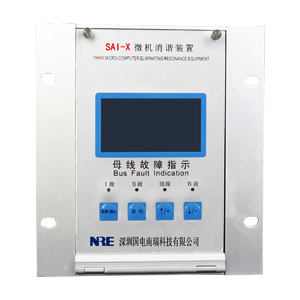
SAI series of computer harmonic elimination device is the company for voltage transformer (PT) users due to the power sector and ferromagnetic resonance eliminator and often fatal accidents occurred burn or explosion , and developed an intelligent harmonic elimination device . The device uses an ARM processor as the core processing elements of the device , the device has a stable performance, strong anti-interference ability and so on . Not only can eliminate the ferromagnetic resonance , can also over- voltage , single phase to make alarm indication.
Second, the model described
Third, technical indicators
( 1 ) Power Supply : AC / DC80 ~ 250V, power consumption is less than 15W;
( 2 ) Ambient temperature : -45 ℃ ~ +50 ℃;
( 3 ) Humidity : less than 90% RH;
( 4 ) eliminate the resonant frequency : 17Hz (1/3 divider ), 25Hz (1/2 divider ), 50Hz ( frequency ), 150Hz (3 octave ), 300Hz (6 octave ) .
Fourth, the device features
( 1 ) for a variety of voltage levels , a variety of resonant frequency ( 1 / 3 frequency , 1 / 2 frequency , frequency , 3 octave , 6 octave ) for a wide range ;
( 2 ) without tuning and debugging , running automatically after power , little maintenance ;
( 3 ) can be distinguished ferromagnetic resonance , over-voltage , single-phase ground ;
( 4 ) automatically display and record single phase, ferromagnetic time and related parameters ( the resonant frequency, amplitude ) resonance occurs ;
( 5 ) can store 100 times fault information for recall and display, power-down 100 -year data is not lost ;
( 6 ) can be configured RS485 communication interface , standard MODBUS protocol ;
( 7 ) All alarms are available relay contact output.
Fifth, the device hardware configuration
1 , Power supply: The device uses high-frequency switching power supply, with strong anti-jamming capability , allows the input voltage fluctuation range of features , the output voltage of DC +5 V, ± 12V.
2, the control center of the device , using the latest ARM processor , with a strong ability to control , operational safety and reliability. And with internal watchdog timer , you can always escape the phenomenon of software failure caused the crash , as the long-term safe and reliable operation to provide a guarantee ;
3, data memory , using the latest Flash memory chips, a large storage capacity , non-volatile data , etc. ;
4 , the data collection : its function is to convert analog to digital to prepare for computer processing ;
5, display parts: the system clock under conditions of normal use , when the system fails , you can display information about the fault ;
6 , harmonic elimination control: harmonic elimination circuit , starting power harmonic elimination device , used to quickly eliminate the ferromagnetic resonance frequency.
Sixth, the device works
This device uses ARM processor as the core element of the PT open delta voltage ( ie, zero-sequence voltage) escape ring detection. Under normal operating conditions , the voltage is less than 30V, power harmonic elimination device ( SCR ) within the device is in blocking state , without any impact on the system . When PT open delta voltage greater than 30V, description of system failure . Began to open delta voltage devices for data collection . Digital measurement , filtering, amplification, digital signal processing , and analysis of the data , calculate , determine the current fault status. If there is some kind of ferromagnetic resonance frequency , CPU immediately start harmonic elimination circuit ( so thyristor ) to allow the rapid disappearance of ferromagnetic resonance in a strong damping. After the elimination of ferromagnetic resonance , CPU corresponding record , store , and automatic alarm , display information about the resonance (including time of occurrence, frequency, amplitude , etc. ) . If the over-voltage or single- phase ground , CPU diagnosis is made , the device displays and alarms are given and automatically records, stores information about the fault . Finally , CPU returns to the initial state , and continues to open delta voltage detection .
Seven, device software constitutes
This device uses the C language as preparation software, the software is mainly composed of the monitoring program , floating point libraries, diagnostic software , harmonic elimination , records and other parts. Real-time monitoring program is completed by the voltage detection , sampling, diagnosis , harmonic elimination , clock, keyboard commands and other display tasks. Simple block diagram is shown in Figure 1 :
Eight, equipment installation
The device is mounted on PK -screen terminal box or according to user selection of cases for each device can access the bus segment 1 to 4 . After the device terminal wiring diagram shown in Figure II :
(1) "1PT *" and "1PT" respectively, then the first paragraph of the same name open delta voltage bus terminal and non-dot end , "2PT *" and "2PT" respectively, then the second paragraph of the same name open delta voltage bus terminal and non- dot end , and so on ;
(2) "RS485" terminal for the communication terminals , direct access to the RS485 communication bus ;
( 3 ) "Power " terminal can be connected to AC power , but also regardless of polarity DC power supply , the voltage ranges are : 80 ~ 250V;
( 4 ) "Ground Alarm " terminals connected to external alarm signal , a pair of normally open contacts when the terminal trouble . When a fault occurs close to the fault disappears delay of about one minute . Its contact capacity AC 220V/5A;
( 5 ) " resonance Alarm " terminals connected to external alarm signal , the terminal when no fault is a pair of normally open contacts . Closed when a fault occurs , the contact capacity AC 220V/5A.
SAI computer harmonic elimination device back terminal diagram
1
4PT *
12
Grounding
2
4PT
13
Power supply
3
3PT *
14
Power supply
4
3PT
5
2PT *
6
2PT
7
1PT *
15
Resonant alarm 4
8
1PT
16
Resonant alarm 3
17
Resonant alarm 2
18
Alarm 1 resonance
19
Resonant common alarm
9
RS485 to
20
Ground alarm 4
10
RS485B
21
Grounding Alarm 3
11
RS485A
22
Ground Alarm 2
23
Grounding Alarm 1
24
Common ground alarm
Nine , instructions for use
1, the device is turned on display :
2 , press the " MENU / OK" button , the LCD panel displays :
3 , by "↑ / +" buttons and "↓ / -" button to move the cursor ;
4 , when the cursor select the " adjustment time " , press the " MENU / OK" button , the LCD panel displays the following :
By "↑ / +" buttons and "↓ / -" button to adjust the cursor to select the numbers, the adjustment is completed after pressing the " Menu / OK" button , the device is shown below :
Behind the adjustment method mentioned above, all the adjustment is completed , the device is shown below :
Press the " Cancel" button to exit the time adjustment.
5 , when the cursor select "Adjust start voltage" , press " Menu / OK" button , the LCD panel displays the following :
By "↑ / +" buttons and "↓ / -" button to adjust the cursor to select the numbers, the adjustment is completed after pressing the " Menu / OK" button , the device is shown below :
And so on , you can adjust all the bus voltage to ground and resonant action , when all adjustments are completed, press the " Cancel" button to exit the " start voltage adjustment " menu ;
6 , when the cursor select the " Communication parameters " , press the " MENU / OK" button , the LCD panel displays the following :
The baud rate of " 600/1200/2400/4800/9600/14400/28800 " to choose from, by "↑ / +" buttons and "↓ / -" button to adjust the cursor to select the number , press the adjustment is completed . " menu / OK " button , the device is shown below :
Mailing address from 0-255 to choose from, after adjustment is completed, press " Menu / OK" button to confirm the adjustment , press the " Cancel" button to exit the "Communication Preferences" menu ;
7 , when the cursor select the " View Fault record" , press the " MENU / OK" button , the LCD panel displays the following :
By "↑ / +" buttons and "↓ / -" button to view the fault recording device , press the " Cancel" button to exit the "Communication Preferences" menu .
8 , press the " Cancel" button for 5 seconds , you can clear all the fault of the recording apparatus , the LCD panel displays the following :
Ten, device installation
Devices with embedded mounting hole dimensions are as follows :
