


PRODUCT SHOW
High-frequency switching DC power supply cabinet
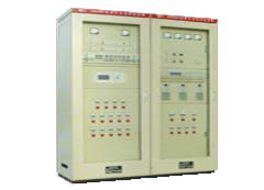
Brief introduction
GZDW series of computer controlled high-frequency switching DC power supply cabinet is the introduction of advanced inverter technology, combines years of practical experience , collected all of the strengths of the original generation of microcomputer control GZDW series developed on the basis of the DC power cabinet products.
Features
With both charge, floating charge state selection , easy adjustable voltage , current limiting and a stable steady flow pressure limiting function selection .
Computer monitoring unit with large LCD display , has a good user interface. Speaking to display the full range of parameters of the battery capacity, battery voltage, charge current , controlling mother voltage, load current, and DC systems.
Has good flow properties are running multiple modules can be individually variable hot plug any one module without affecting the normal operation of other modules.
Practical performance
Since this series of products from the market , run by each substation practice outside the province , has been well received , are that: the product of advanced technology indicators , steady flow of high precision , low ripple factor , small size , high power, stable performance , reliable operation, set various functions as a whole, which enables remote centralized four remote , comprehensive benefits , and apply the unattended substation .
The main technical indicators
Input voltage : AC380V ± 15%, 50 ± 5% HZ
Output voltage : DC2200V, DC110V, DC48V
Output Current : 10,20,30,40,50,60,100,200 A
Regulation accuracy : ≤ ± 0.5%
Steady flow several times : ≤ ± 0.5%
Ripple factor : ≤ ± 0.1%
Machine Noise : ≤ 55DB
Cooling: Intelligent cooling , natural cooling
Work: continuous work
NARI is a professional company engaged in research and development of high-frequency switching DC power supply , the production company, with highly qualified development team, extensive field experience , developed for all types of high-frequency switching DC substation systems and related equipment ; product has been widely applied from 35KV to 550KV substation different voltage levels , power plants , and opening and closing .
Module uses the most advanced technology edge resonant soft-switching technology , hot-swappable , using isolation between the module and the module design to prevent mutual influence between modules ; internal module comes with CPU, module calibration and control of all benchmarks used in all 12 D / A is completed, replace all potentiometers to avoid potential parameters inherent temperature coefficient and mechanical properties caused by the drift ; make high precision control module to adjust a bit, the module 's output voltage change of only a dozen millivolts ; in addition , the module also built E2ROM, to ensure that the operating parameters of the module is never lost , even from its main operating parameters of the monitoring work will not be any change.
Monitoring system uses modular structure design , divided into: a master central monitoring , communication monitoring unit, DC monitoring unit , switch monitoring unit , also based on the need optional battery inspection unit and insulation testing unit , each unit through the RS485 port and central main monitor is connected , this modular design makes maintenance very simple and quick ; monitoring system with intelligent " four remote" interface has been done interface, communication protocol with many automation equipment can be modified at any time according to user requirements .
I developed JY insulation monitoring unit , using non -contact DC micro current sensor , the use of positive and negative bus to ground leakage current of grounding resistance generated by the bus on the way to measure the size of the grounding resistance , thereby discriminating ground fault bus . This technique without any signal superimposed on the bus will not have any adverse effect on the DC bus powered by a bus on the complete eradication of distributed capacitance caused by false positives and false negatives , and be able to accurately determine the complex grounding ground support road.
In order to ensure the reliability of the product, I guarantee the device off , all imported key components of plant components, such as:
· High-frequency transformers , high-frequency inductor cores using the German company Siemens and skeleton , UK Copperbelt .
· MOSFEET high frequency switch, fast recovery tube using the company's products in Germany IXYS
· High-frequency switching controller chip used by the U.S. company's products UNITRODE
· CPU used by the U.S. INTEL80C32, ATMEL89C52
· HP's HCNR200 linear optocoupler
Precision resistors manufactured by Japan Metco accuracy of one-thousandth of resistance, etc.
· Texas company producing 12 D / A, 12 bit A / D
A DC system configuration scheme
1.1 with YM22005, YM11010 system configuration consisting of optional equipment such as program instructions Scenario 1 Scenario 2
YMWK-1 main monitor √ Scenario 1:
Using characters LCD display , optional battery inspection , insulation testing and buck module.
TPC touch screen controller √
TPC-A AC monitoring √ √
TPC-D DC monitoring √ √
TPC-K switch monitoring √ √
TPC-M module monitors √ √ 2:
Using touch screen control , optional battery inspection , insulation testing and buck module.
YM22005, 11010 rectifier module √ √
TJ05? Module bay √ √
TPC-B battery inspection Optional Optional
TPC-J insulation testing Optional Optional
J10H (J15L) Buck Module Optional Optional
1.2YM22010. YM11015 up the system configuration is as follows
Optional Equipment
Scenario 1
Scenario 2
Program description
YMWK-1 main monitor
√
Scenario 1:
Using characters LCD display , optional battery inspection , insulation testing and buck module.
TPC touch screen controller
√
TPC-A AC Monitoring
√
√
TPC-D DC monitoring
√
√
TPC-K switch monitoring
√
√
YM22010, 11015 rectifier
√
√
Solution 2 :
Using touch screen control , optional battery inspection , insulation testing and buck module.
TJ10-4 (TJ10-3) module bay
√
√
TPC-B battery inspection
Optional
Optional
TPC-J insulation testing
Optional
Optional
J10L? Buck module
Optional
Optional
2 DC battery management system
DC battery system is an important part of maintenance of the battery pack and monitoring well is particularly important. TPC intelligent high-frequency switching DC system with advanced battery management functions ; may be strictly in accordance with the battery charge-discharge curve of the battery management.
The battery management system has the following features:
2.1 charging function
According to the charging system monitoring parameter settings, automatic battery charging process is completed , the data set based on the use of the battery charging parameters type, capacity , and provided by the manufacturer ( nickel-cadmium batteries and valve- sealed lead-acid battery charging process has some differences ) .
1 nickel-cadmium batteries run diagram shown below , the charging procedure is as follows :
a, a nickel battery normal charge procedure: with 0.2C5A ( can be set ) constant current charging , charging voltage reaches the set value are (1.47-1.55) V × n (n is the number of single battery section ) , the computer control device charging floating charge automatically converted to constant voltage charging, when the charge current decreases , reaching 0.02CA ( can be set ) , and then continue charging 3h, float charging device running automatically converted floating charge voltage of (1.36-1.45) V × n ( can be set ) .
b, long-term floating charge procedure:
Under normal operating floating state every 1-3 months , the computer control system automatically transferred to the constant current charging state run by rechargeable nickel-cadmium batteries normal procedure for charging.
c, AC interrupt routine :
During normal operation of floating charge state, when power outage , then charging float charging device stops working , the battery module through the buck , without interruption to the power transmission control bus . When the battery voltage is below the set limit alarm system monitoring module audible alarm.
d, AC Power Recovery Program :
AC Power restore power operation, microcomputer control the charging device automatically enters the constant current charging state run by rechargeable nickel-cadmium batteries normal procedure for charging.
2 , VRLA batteries run diagram shown below , the charging procedure is as follows :
a, normal VRLA battery charging process .
With 0.1C10A ( can be set ) constant current charging , the voltage reaches the setting value (2.30-2.40) V × n (n is the number of single battery section ) , the computer controls the charging device automatically converted floating charge voltage charging , when the charge current decreases , reaching 0.01CA ( can be set ) , the computer start time , 3h , the microcomputer controls the charging device automatically converted to float floating charge state operating voltage of (2.23-2.28) V × n.
b, long-term floating charge procedure:
Under normal operating floating state every 1-3 months , computer controlled charging device automatically transferred to the constant current charging state run according to normal VRLA battery charging process for charging.
c, AC interrupt routine :
During normal operation of floating charge state, when power outage , then the charging device to stop working , the battery module through the buck , without interruption to the secondary control bus transmission. When the battery voltage is below the set limit alarm system monitoring module audible alarm.
d, AC Power Recovery Program :
AC Power restore power operation, microcomputer control the charging device automatically enters the constant current charging state run according to normal VRLA battery charging process for charging.
2.2 battery temperature compensation
VRLA batteries at different temperatures on the battery charge voltage must be adjusted accordingly in order to protect the battery in the best condition , the battery management system can monitor the battery temperature ; user based on the parameters provided by the battery manufacturer , choose to use the battery temperature after the compensation function , select this function the system monitors the battery temperature , battery charging voltage is automatically adjusted so that the battery in the best condition .
2.3 Battery periodic maintenance functions
When the battery is not a long-term or long-term floating state , the battery plate active material is very easy to cure , when the active substance getting low, the battery discharge capacity is also getting worse, until it put no electricity.
In addition, because the actual voltage discrete, single cells and between cells of different battery float voltage is only a nominal mean , selected float voltage does not meet the requirements of each cell , if the battery is long-term floating state , the result must be , in part to ensure the battery is full , but there is a part of the battery is not full , this part of the battery voltage is manifested virtual, need to discharge , the discharge capacity is poor.
Therefore, the requirements of the battery charging system with periodic maintenance are charged for the activation function , in order to avoid sulfide battery , false charge, make sure the battery discharge capacity and service life.
My company's TPC control system, can be very easy to achieve this function, and regularly charging intervals are set by the user according to their own needs .
3 Monitoring System
3.1 Monitoring system functions and composition
Main functions and features 3.1.1 Monitoring System
Monitoring system to control the entire DC system , management of the core ; main task is to monitor the system : the system of each functional unit and batteries for long-term automatic monitoring , access to the system in a variety of operating parameters and status , according to the measurement data and real-time operating status processing, and as a basis to control the system to achieve precise automatic power management system, thus improving the reliability of the power system to ensure its continuity , safety and reliability work. Monitoring system has " telemetry, remote , remote control , remote adjustment " four remote capabilities to meet the requirements of plant automation and electrical systems unmanned substation ; equipped with a standard RS-232 interface for easy inclusion power plant automation system.
3.1.1.1 The main features of the monitoring system
● monitoring system uses a microprocessor as the core of distributed control systems , modular design ; against AC distribution , DC feed , rectifier and battery packs implement a full range of monitoring and control.
● The large LCD display , CCFL backlight , to achieve full Chinese display , in addition to completing regular data measurement , real-time display of power system operation , but also offers a variety of menus , information, tips , truly interactive operation.
● keyboard can easily adjust the system operating parameters and various control parameters for manual management and control system implementation , simple and convenient.
● via the display , lights and sound and light alarms provide a variety of work status , fault type, fault location indication ; system can accurately locate the fault , the system maintenance is simple and effective.
● monitoring system software and hardware open design , you need to be ready to add, modify parameter measurement and control monitoring system based on different users .
● The battery voltage, charge and discharge currents of precise management and strict control is the key to protect the battery and prolong battery life , for which the monitoring module according to charging parameters ( such as voltage protection value , the charging current limit values set by the user maintenance BC interval , etc. ) , adjust the charging mode rectifier modules , charge current, accurate auto- complete battery management and maintenance.
● The battery temperature compensation function , maintenance-free battery charging voltage with changes in ambient temperature needs to be adjusted in order to protect the battery in top working condition , prolong battery life. The monitoring module can automatically complete the battery temperature compensation to ensure that the battery in the best condition .
3.1.1.2
● Monitoring Dual AC power supply voltage and AC contactor status : When the power down all the way to the grid , the grid voltage is too high or too low, unbalanced three-phase power supply automatically when the system is switched to another concurrent sound and light alarm .
● rectifier output current detection and fault status : When the module is faulty , the monitoring system audible alarm signal and re- sharing rectifier load.
● The local or remote control rectifier on / off , automatic control battery charging float conversion .
● The continuous local or remote setting module output voltage. Monitor the feed output DC voltage, current , each feed output switch status, fuse status , module status insulating state , and Buck , an exception occurs when the audible alarm .
● monitoring the battery voltage and charge and discharge current : When utility power fails to maintain power to the load from the battery if the battery voltage drops below the value of the low-pressure alarm , audible alarm monitoring module ; When utility power is restored the battery monitoring system can automatically balance charging management ; If the battery is long-term floating state for maintenance battery ( the time set by the user , the default is 720 hours ) , in order to maintain the battery capacity at a certain time for a balanced charge . When you consider it necessary to charge the battery were also manual equalization charge through the keyboard.
● The Ministry of standard communication protocols , RS232 serial communication interface , can be easily automated docking system with the power to realize the power system, " remote telemetry , remote control , remote adjustment ," the four remote functions .
● monitoring system provides information on important faults 6 relay normally open, normally closed contact output when used for user needs, fault information the user can choose the main monitor .
3.1.1.3 Monitoring System " four remote" amount
● remote measurements
Two three-phase AC voltage , AC current
Voltage co-parent , female-controlled voltage control, current , battery voltage, battery charge and discharge current , temperature, cell voltage
● Remote Communication
AC contactor status
Module status information
Closing switch tripped, the control switch trip , the battery fuse broken
● Remote amount
Each module on / off , system were / Float
● remote adjustment amount
Charge voltage , float voltage , controlling voltage
3.1.2 Monitoring System hardware architecture
● monitoring system uses modular hardware architecture distribution structure, function relatively independently of each unit , unit failure does not spread in the system, thus the system has high reliability.
● monitoring system uses three control management structure, monitoring system block diagram shown below , the highest level of system control backstage or power automation system , and system monitoring via RS232 module ; system monitoring module for the monitoring system of the second stage , underlying monitoring system from the AC power distribution monitoring unit, module monitoring unit and the DC feed units.
● system monitoring module via RS485 communication interface with AC power distribution monitoring unit , each module monitoring unit and the DC feeder connected to the monitoring unit . AC power distribution monitoring unit, module monitoring unit and the DC feed internal units using microprocessor technology , which monitors the operating parameters and working status of each component , the control command sent from the host monitor , is the basis of the monitoring system .
3.2TPC touch screen control system
3.2.1 Overview
TPC (Touch panel controller) monitoring system controls the entire DC system management center ; main task of the monitoring system are: the various functional units of the system and automatic battery for long-term monitoring , access to the system in a variety of operating parameters and status , according to the measurement data processing and real-time operating status , and as a basis for system control, automatic precise power management system, thus improving the reliability of the power system to ensure its continuity , safety and reliability work.
TPC monitoring system has " telemetry, remote , remote control , remote adjustment " four remote capabilities to meet the requirements of plant automation and electrical systems unmanned substation ; equipped with a standard RS-232 interface , can be easily incorporated into power plant automation system.
TPC monitoring system features:
☆ using a microprocessor as the core of distributed control systems , modular design ; against AC distribution , DC feed , rectifier module, battery pack and slip the insulation system implementation of comprehensive monitoring and control.
☆ using large-screen touch-screen control , CCFL backlight , to achieve full finished display , in addition to completing regular data measurement , real-time display of power system operation , but also offers a variety of menus , information, tips , touch-screen operation , the real man-machine dialogue operation .
☆ via the display , lights and sound and light alarms provide a variety of work status , fault type, fault location indication ; system can accurately locate the fault , the system maintenance is simple and effective.
☆ monitoring system software, hardware, open design , you need to be increased at any time according to different users , modify the parameters of measurement and control monitoring system .
☆ a monitoring system to support dual battery pack , the bus segment monitoring mode , automatic management of dual battery charging two batteries completely independent management to ensure system security.
☆ battery voltage , charge and discharge currents of precise management is critical to protect the battery and prolong battery life , for which the monitoring module according to charging parameters ( such as voltage protection value , the charging current limit set by the user , maintenance intervals are filled charging mode time, etc.) , adjustment module , the charging current , accurate auto complete management and maintenance of battery maintenance .
☆ battery temperature compensation function , maintenance-free battery charging voltage with changes in ambient temperature needs to be adjusted in order to protect the battery in top working condition , prolong battery life. The monitoring module can automatically complete the battery temperature compensation to ensure that the battery in the best condition .
3.2.2 The main functions of the monitoring system
☆ Dual AC power supply voltage monitoring and AC contactor status : When power down all the way to the grid , the grid voltage is too high or too low, unbalanced three-phase power supply automatically when the system is switched to another concurrent sound and light alarm .
☆ rectifier output current detection and fault status : When the module is faulty , the monitoring system audible alarm signal and re- sharing rectifier load.
☆ local or remote controlled rectifier on / off , automatic control battery charging float conversion .
☆ continuous set of local or remote output voltage of the module , the current limit value.
☆ monitor the feed output DC voltage, current , each feed output switch status, fuse status , module status insulating state , and Buck , an exception occurs when the audible alarm .
☆ monitors the battery voltage and charge and discharge current : When utility power fails to maintain power to the load from the battery if the battery voltage drops below the value of the low-pressure alarm , audible alarm monitoring module ; When utility power is restored the battery monitoring system can automatically balance charging management ; If the battery is long-term floating state for maintenance battery ( the time set by the user , the default is 720 hours ) , in order to maintain the battery capacity at a certain time for a balanced charge . In addition, when a user deems it necessary to charge the battery all the time , but also by key operation manual equalization charge .
☆ support two battery inspection , single battery monitoring with overvoltage , undervoltage and differential pressure alarm function , accurate troubleshooting battery.
☆ provides silicon chain control port that supports 5 , 7 silicon chain automatic control.
☆ slip insulation monitoring support bus section , slip insulation resistance is too low alarm .
☆ using standard communication protocols Ministry , RS232 or RS485 serial communication interface, support 1200BPS, 2400BPS, 4800BPS, 9600BPS baud rate , can be easily automated docking system with the power to realize the power system, " remote telemetry , remote control , remote adjustment " the four remote functions .
☆ fault monitoring system for important information provided six groups normally open relay contact output , fault set their own content according to user needs .
3.2.3 Monitoring System Components
The basic configuration consists of the main monitoring system monitoring , communication monitoring unit, DC monitoring unit , digital I / O units. Optional battery unit patrol unit , insulated slip detection unit . The above configuration covers all the DC system monitoring and control functions ; system block diagram as follows :
3.2.4 Main Monitor
3.2.4.1 Function
Provide human interface , large screen LCD display and touch screen display for system operating parameters , system control and system operating parameters .
Monitoring unit provides RS485 communication, reading monitoring unit parameters.
Provides RS232 or RS485 and PC communications or automation system provides DC system operating parameters.
Real-time clock provides accurate time .
System parameters with power-down protection. System settings and control parameters will not be lost after the monitor power down .
3.2.4.2 Block diagram and interface diagram
TPC main control interface specification
Serial Interface
Interface Definition
Interface Description
J1
Monitoring supply
1 - Power n 2 - empty 3 - Power Negative
Input voltage (90V - 320V DC)
J2
PC
Communication
2-232TXD ,3-232RXD ,5-GND
6-485A ,7-485B
LED
Indicator
Work lights ( flashing work)
J3
RS485
1-485A, 2-485B
JP1
232 /485 Select
Jumper selectable , select the host computer communication
( On the motherboard , factory defect 232 mode )
There are high voltage, maintenance operations should pay attention to safety on the J1.
3.2.4.3 Main Monitor Installation Instructions
Just install the main monitor prescribing hole mount comes with the main monitor left-right asymmetry , hole location should be determined according to the panel with the cutout hole location diagram .
Hole size chart:
Panel with cutout diagram :
3.2.4.4 Main Monitor Operating Instructions
LCD Screen structure:
The entire display consists of four parts : the header bar, the main window area , the menu bar and additional bar. Figure 1 :
Header bar displays the company name and the date and time.
The main part of the main window area of the display screen , the display of the specific content of the menu bar , such as system status information, fault information, system parameter settings , the system control parameters.
The menu bar provides four main menu or the numeric keypad.
Additional columns mainly to provide some additional information , such as: up and down , save and exit button ; display system settings of the current input data and prompt information and operating results ( such as: saving operation success or failure ) and so on.
Actions menu consists of:
System is divided into four main menus , namely: the main window of information , information, system settings, system control, are shown in the menu bar .
Main window information ? Including system status ( normal or fault ) current information and systems , through the upper and lower flip to switch one , Sec bus and one or two set battery parameters .
Information query ? Menu, you can query the AC and DC parameters, the module parameters , insulation monitoring parameters , the current fault , fault history , battery inspection parameters , discharge metering and system settings, control information and other projects directly in the main window area touch check the corresponding items of its specific content.
System Settings ? Input system after setting a password to enter the system setup page , including AC and DC settings , modules , communication , time, password settings, battery inspection , insulation monitoring , silicon chain settings , and brightness adjustment.
System control ? Can control the batteries are , float switch and the module . Specific operation in Figure 2.
Figure 2
Basic Instructions:
System uses a window display , touch- operation, thus easily complete a friendly dialogue between man and machine , and with operating prompts , the operation is simple, easy , and straightforward.
When the system power on, shows the company logo, company basic information, and time and date . As shown in Figure 3 , which includes business address, telephone number and fax number , user contact with the manufacturers . At this point, if the tap anywhere on the screen , then enter the "Main Window Information" page .
Figure 3
Main window information ? Display system status ( normal or fault ) and DC parameters , the display screen as shown in Figure 4 . If the bus is equipped with two sets of segments or cells, the main window displays the information from the two pages of DC parameters or on the cell parameters were two bus can tap " Next " button queries the appropriate parameters. If the system fails, the system status is displayed as " failures " and blinking , and with a sound alarm. Direct Touch " failure " can be found at the current fault information . In the menu bar, tap the corresponding menu in the main window of information pages respectively to enter the " information search ", " System Settings" , "System Control" window.
Figure 4
In the information query page can query the system operating parameters and system settings data . Including AC and DC parameters, the module parameters , the current fault , fault history , system setup parameters, system control parameters, discharge measurement , as well as insulation monitoring and battery inspection parameters. In the main window area displays the corresponding information query options , you can check in directly touch the corresponding option on its specific content , shown in Figure 5 .
Figure 5
AC parameters shown in Figure 6 , including the exchange of one , Road input phase voltage, AC current, two -way road contactor status ( working , backup ) and ambient temperature.
Figure 6
DC parameters shown in Figure 7 , including the co-parent voltage control bus voltage control, current , battery voltage, current, and battery status ; If you set two segments bus or two batteries can be ' on ' Next Page ' , respectively, look .
Figure 7
Module parameters shown in Figure 8 , each page displays the relevant parameters of the four modules , including modules voltage, current , switch status, and power supply module is a piece co-parent , female -powered or controlled an aggregate Sec female power .
Figure 8
Insulation monitoring as shown in Figure 9 , showing co-parent , female-to- ground resistance to control voltage and fault slip values. Resistance values indicate positive ground , negative for negative ground . Can display up to seven slip faults. If the number of segments insulation monitoring bus is set to 0 , you can not enter this page, if set to 1 , then the " Next " button is invalid.
Figure 9
Battery inspection shown in Figure 10 , the display of each group in each of the battery cell voltage and temperature ( n = 2 temperature ) , shows up to 19 batteries. If the number of patrol group is set to 0 , you can not enter the page, set to 1 , then on the next page button is invalid.
10
Figure 11 is measured discharge time monitoring discharge of the battery groups , including the discharge voltage, discharge current, discharge capacity and discharge time , may touch the "Start / Stop" switch to start and stop measurement of the discharge , or touch "Clear" button twice to clear the discharge capacity and discharge time , when the battery is charging , the system automatically pause timing, counting.
Fault current fault information display system currently exists , displays up to 12 , fault history shows faults happened before and has now been ruled out of . System setup parameters and system control parameters and system settings, system control content the same, but only query can not change the contents of each parameter .
11
System setup is complete the system will automatically set the parameters necessary for management , automated management system is the basis of illegal changes may cause serious harm , and therefore the necessary permissions to manage the operation , that is set before you enter the correct password , the password input page shown in Figure 12 after the correct password is automatically entered into the system set up five pages . Factory set password is " 12345" , when the user changes the password in the system settings , must be 5 .
12
System Settings page shown in Figure 13 , the main window area with selection buttons for each setting item , tap directly into a corresponding set operation.
13
AC settings shown in Figure 14 , you can set the AC power supply is the first way , the second way or two-way co power supply , AC overvoltage and undervoltage value and exchange value . When you set the AC power supply, the first point of contact " first way" main window area , then those words would become anti- color display , if the tap again , will become the "second way" , the next touch becomes " dual " until the parameter you want to set up . When setting the value of the AC overvoltage , overvoltage first touch behind the parameter value " 250.0 " , so that it is selected, and then enter the parameter value to be set in the numeric keypad , the data you enter will be displayed in an additional column out until a complete data input automatically after you enter the data covered the main window area of the corresponding parameter .
After set up , you can tap the "Save" button to save your data set , or touch "Exit" to exit without saving "Communication Settings" , then set the parameters of the exchange will restore the previous value.
14
DC set up as shown in Figure 15 , you can set the DC bus segment or segments , controlling mother output voltage, overvoltage value co-parent , , co-parent undervoltage value , controlling mother overvoltage value , controlling mother undervoltage value. The setting method "communication settings" same .
15
Module settings shown in Figure 16 , set the number of modules. Up to 16 modules.
Module number setting range is 1 to 16.
Figure 16
Battery management shown in Figure 17, you can set the number of battery packs ( up to two ) , charge voltage , float voltage , charge current limit , switching current , timing are charging time , charging all the time limit , maintaining both charge time temperature compensation coefficient , low battery voltage values.
17
Battery inspection shown in Figure 18 , you can set the number of patrol group , the number of cells , single cells , under-voltage value, and the value of the differential pressure alarm , tail number of batteries, battery over-voltage value of the tail .
Figure 18
Insulation monitoring bus 19 is set to monitor the number of segments as shown , differential pressure alarm value , alarm grounding resistance value .
19
Communication settings shown in Figure 20 , you can set the system address, baud rate and protocol , baud rate setting method is to first select the " Baud rate " that touch "1200 ", touch the position again , will change to " 2400 ", " 4800 ", " 9600" , until the value you want to set the rate so far , and then press "Save ." RTU communication protocol optional protocol , MODBUS protocol , IEC CDT agreement or statute .
Figure 20
As shown in Figure silicon chain settings , set the silicon chain progression ( 5 , 7 , or no silicon chain ) , the definition of the brightest fault output specific fault type 21.
Figure 21
Defines the number of various types of failure shown in Figure 22 . Just enter the number corresponding to a fault , press the OK button .
If the silicon chain is set to 5 or 7 , then 04,05,06 output invalid ( auto-hide ) .
Figure 22
Time password settings as shown in Figure 23 , you can set the system to set a password , the system control password and date and time. ( 16888,10220 )
Figure 23
Other can set the brightness of the LCD screen in other settings page, if you press the "Save " button , then the next time the system is powered on , the brightness of the display according to save it, "exit" based upon the brightness of the display settings .
Figure 24
System control can control the battery charging method ( average charge, float ) and modules open, shut down . After pressing the save machine , control effect.
Figure 25
System Setup parameters
Range:
To ensure system security, when setting the system parameters , the system automatically checks the changed parameters , the range of parameters if the input is not required , the system will prompt set incorrectly . The setting range of the parameters shown in the following table :
Parameter name
Typical values
Setting range
Parameter name
Typical values
Setting range
AC overvoltage values
253.0V
220 ~ 264V
Are charging pressure
252.0V
220 to co-parent overvoltage values
AC undervoltage value
187.0V
160 ~ 220V
Float voltage
240.0V
220 to co-parent overvoltage values
Mother output voltage control
220.0V
198 ~ 242V
Charging current limit
20.0A
1 ~ 200A
Co-parent overvoltage values
264.0V
220 ~ 320V
Timing are charging time
3.0 hours
0 to 4.2 hours
Co-parent undervoltage value
198.0V
170 ~ 220V
Switching Current
2.0A
0.5 ~ 20.9A
Mother overvoltage control value
242.0V
220 ~ 250V
BC limited time
18 hours
5 to 36 hours
Mother undervoltage control value
198.0V
170 ~ 220V
Maintenance are charging time
90 days
20 to 99 days
Battery voltage value
187.0V
160 ~ 220V
Temperature compensation coefficient
0.3
0 to 1.0
Number of modules
04
01 ~ 16
Number of battery inspection group
0 Group
Group 0-2
The number of battery packs
Group 1
Groups 1 and 2
A number of cells
19
1 ~ 19
Second set of batteries sessions
19
1 ~ 19
Insulation monitoring the number of segments
0 section
Paragraphs 0-2
Single battery overvoltage values
15.50V
1 ~ 21V
Insulation value of the differential pressure alarm
50.0V
20 ~ 99.9V
Single battery voltage value
10.50V
1 ~ 21V
Grounding resistance alarm
30.0
10 ~ 50
Patrol differential pressure alarm
0.99V
0.1 ~ 0.90V
Mailing Address
01
01 to 99
4 basic monitoring unit
4.1TPC-A AC monitoring unit
4.1.1 Function
Dual -phase AC input voltage measurement , one current , AC contactor state.
Will be transmitted via RS485 serial interface detection information to the main control, monitoring and management as the main power system and process fault alarm basis.
AC input voltage is switched automatically according to the measurement of auto-complete dual AC input ; achieve the dual exchange mutual backup power supply.
Direct access to the voltage measurement , current measurement using a 50 /5 current transformer measurement.
4.1.2 Block diagram and interface diagram :
AC Monitoring Unit Interface Description
Interface Serial Interface Definition Interface Description
J1 AC current 1,2 - ? Alternating current transformer input
J2 one AC voltage 1 - zero line input ; 3-A phase voltage input
5-B phase voltage input ; 7-C phase voltage input
J3 Monitor Power 1 - Power n 2 - empty 3 - Power Negative
Input voltage (90V - 320V DC)
J4 Road AC voltage 1 - zero line input ; 3-A phase voltage input
5-B phase voltage input ; 7-C phase voltage input
J5 AC contactor control 1,3 - A Way AC contactor control
5,7 - B -way AC contactor control
J6 amount of a state , all the way contactor status ; 2 , Road contactor status
3 , mine status , 4-8 , AC switch status
9, the state quantity measuring common
LED lights work lights ( flashing work)
J7 RS485 1-485A ,2-485B
RV1 potentiometer to adjust the way the A-phase voltage measurement
RV2 potentiometer to adjust the way the B-phase voltage measurement
RV3 potentiometer to adjust the way the C-phase voltage measurement
RV4 Road A potentiometer adjustment phase voltage measurement
RV5 potentiometer Road B -phase voltage measurement regulation
RV5 potentiometer Road C -phase voltage measurement regulation
J2, J4 and J5 220V has the AC voltage , maintenance operations can be carried out after the first cut off the two AC inputs , to ensure safety.
There DC high voltage , maintenance operations should pay attention to safety on the
